If you design parts for sheet metal fabrication, a handful of decisions determine whether your part ships on time or bounces back for rework. This sheet metal design guide covers the sheet metal design guidelines that actually hold up on the shop floor: picking the right thickness, setting a workable bend radius, calculating bend allowance with the K-factor, and choosing tolerances that don't blow your budget. We wrote it the way we'd explain it to an engineer sitting across the table, not the way a textbook would.
What Is Sheet Metal, and Why Does Design Matter So Much?
Sheet metal is flat metal stock, usually somewhere between 0.5 mm and 6 mm thick, that a fabricator cuts, punches, and bends into a finished part. Steel, aluminum, and stainless steel show up most often, and each one reacts differently under a press brake. A design that looks perfect on screen can crack, twist, or simply refuse to fit once it hits the shop floor.
Every decision you make in CAD shapes what happens next in production. Pick the wrong bend radius, stretch a flange too thin, or drop a hole too close to a bend line, and you turn a straightforward part into scrap.
So you require proper sheet metal design rules because manufacturing runs into physical limits that most software won't flag for you.
Machined parts get carved from a solid block, so each feature stands independent of the rest. Sheet metal starts life as one flat sheet, and every bend you add pulls on the material around it. Once you understand how metal actually moves during a bend, the rest of this guide will make a lot more sense.
The Complete Sheet Metal Design Guide: How to Design Sheet Metal Parts for Manufacturing
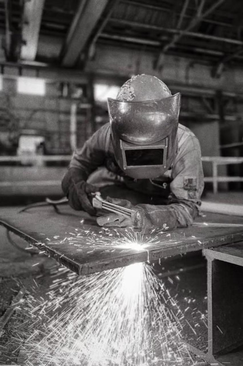
Designing a sheet metal part is about more than getting the final dimensions right. The part also has to survive cutting, bending, forming, finishing, and assembly without cracking, distorting, or requiring unnecessary secondary work. The best sheet metal designs account for those manufacturing constraints from the beginning.
The following design guidelines cover the decisions that have the biggest impact on manufacturability, cost, and part quality, from material thickness and bend radius to flat patterns, tolerances, and feature placement.
1. Start With the Right Material and Thickness
Before you touch your CAD software, answer three questions:
- what does the part need to do,
- what material can handle that environment, and
- how many units do you need.
These answers drive nearly every choice that follows, including thickness, bend count, and finish. Skip this step and you'll likely redo your flat pattern later.
Sheet metal thickness usually goes by gauge number instead of a direct measurement, and gauge doesn't scale the same way across materials. A lower gauge number means thicker metal, but the same gauge number translates to different actual thicknesses depending on whether you're working in steel, aluminum, or stainless.
Commonly used steel sheet metal ranges from 30 gauge, around 0.4 mm, up to about 7 gauge, around 4.55 mm, and the gauge system itself traces back to the British wire industry, well before metric measurement became standard.
That history matters because it explains why gauge charts differ by material. As one working example, 18-gauge carbon steel measures about 0.0478 inches, or 1.21 mm, while 20-gauge measures about 0.0359 inches, or 0.91 mm. Move two gauge numbers and you shift the thickness by roughly a third, so always check an actual thickness chart instead of trusting the gauge number alone.
Stainless and aluminum need their own reference tables too, since neither follows the standard steel gauge chart. For instance, 14-gauge stainless steel measures about 0.0781 inches, or 1.98 mm, while 14-gauge aluminum measures about 0.0641 inches, or 1.63 mm, even though the gauge number is identical.
You'll need to match your gauge to the load the part carries rather than picking whatever thickness looks solid on the screen, and check your fabricator's stocked thicknesses before you finalize the drawing so you avoid paying for a custom mill order.
2. Get the Bend Radius Right
The bend radius is the inside curve created at every fold, and getting it right decides whether your part forms cleanly or cracks. If you choose a radius that's too small and you risk splitting or thinning the metal at the bend; choose one that's too large and the part misses its size targets. Material type, thickness, and bend angle all shape what radius will actually work for your design.
Ductility drives most of this. More ductile metals tolerate tighter bends without damage, while less forgiving materials like stainless steel or high-strength steel need wider radii to avoid cracking, which is why a proper bend radius chart always separates figures by material rather than giving you one universal number.
A common shop rule ties minimum radius to thickness and hardness. For material between 1 mm and 6 mm thick, fabricators usually hold the minimum inside bend radius close to the material thickness itself, moving up to about 1.5 times the thickness once stock reaches 6 mm to 12 mm. Softer materials like aluminum can often go tighter than that, while harder stainless grades need more room to spare.
Look at a material-specific example and the range becomes clearer. Soft aluminum like 3003-O can handle an inside bend radius as small as half the material thickness, while 6061-T6 aluminum typically needs one to three times the thickness, depending on which direction you bend it.
Steel falls in a similar range depending on temper and grain direction, and your fabricator can confirm the achievable radius once they see your material callout.
Precision shops often skip matching radius to thickness altogether and standardize around one practical figure instead. Many precision sheet metal fabricators default to a 0.030 inch inside bend radius for material up to about 0.125 inches thick, since that figure lines up with common press brake tooling and skips the cost of custom dies. Matching the radius exactly to material thickness feels like the intuitive move, but it often forces the shop into expensive custom tooling instead.
A bend radius that's too tight concentrates stress right at the fold. Bend angles under 30 degrees pack even more stress into a small area, which raises the odds of cracking if the radius runs undersized. Once a crack starts, it tends to fail the same way every time the part flexes again, so the fix is usually simple: widen the radius, or split one sharp bend into two gentler ones if your geometry allows it.
3. Understand Bend Allowance and the K-Factor
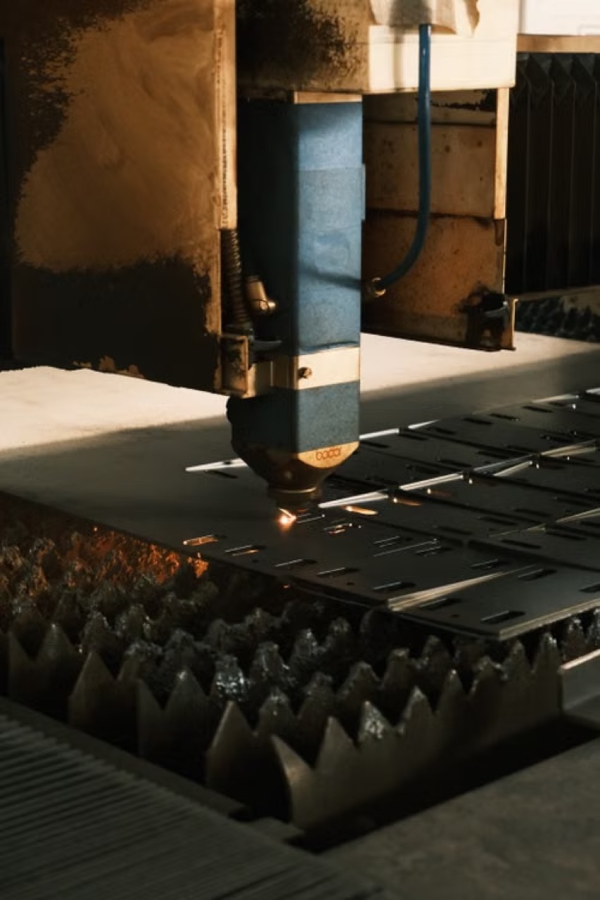
Bend allowance is the extra length of material a bend consumes, and you need this number to build an accurate flat pattern before anything gets cut. Every time metal bends, the outside stretches while the inside compresses, and somewhere between the two sits a line called the neutral axis that doesn't change length at all. The K-factor tells you exactly where that neutral axis sits inside the material thickness.
Getting the K-factor wrong throws off your whole flat pattern. If you don't account for it correctly, your finished lengths likely won't match your CAD model, and you'll end up with wasted parts and extra trips back to the press brake. Nearly every flat pattern your CAD software generates depends on this one calculation running correctly in the background.
The standard bend allowance formula is BA = π × (IR + K×T) × A / 180, where IR stands for inside radius, K is the K-factor, T is material thickness, and A is the bend angle in degrees.
You can run this calculation before you finalize any flat-pattern dimensions, and remember that most CNC press brakes automatically add two to five degrees of springback compensation on top of the formula. Skip the springback adjustment and your formed part will likely land a few degrees off target.
You won't need to run this by hand for every part since most CAD software calculates it automatically once you enter thickness, radius, and K-factor. What matters is knowing what the software is actually doing under the hood, so you catch a wrong default value before it reaches production.
Takeaway: Leaving a default K-factor unchanged for a new material causes more flat pattern errors than almost anything else on this list.
4. Know What Tolerance to Expect
Tolerance defines how far a finished part can drift from its nominal drawing dimension and still work. This is where fabrication cost really lives, because tolerances set out of habit rather than out of actual function create avoidable expense on nearly every job.
Setting tolerance by what the part needs, not by default, is one of the fastest ways to control both cost and quality on a drawing.
Different features on the same part usually call for different tolerance levels. On custom work, the pattern tends to repeat: tight tolerances on the handful of features that mate with something else, and loose tolerances everywhere the fit doesn't actually matter.
A mounting hole that lines up with another part needs precision. A decorative cutout on the same panel doesn't.
Two standards come up on nearly every sheet metal drawing.
- ISO 2768 covers general tolerances for linear and geometric features when the drawing doesn't spell out a specific tolerance
- ASME Y14.5 defines the geometric dimensioning and tolerancing practice used mainly in the United States
What's actually achievable depends heavily on process, not just the standard you cite. Laser cutting a single flat face on thin stock can achieve about plus or minus 0.005 inches, but adding bends loosens that figure fast, since every formed feature introduces its own variation while the part flexes during forming. A drawing with unrealistic tolerances on formed features usually comes back from quoting with questions, not a price.
As a broader reference point, general or structural fabrication for frames and brackets typically runs plus or minus one-sixteenth to one-eighth of an inch, while standard sheet metal fabrication for enclosures and panels runs roughly plus or minus one-thirty-second to one-sixteenth of an inch on formed dimensions.
You can save the tight tolerances for the specific features that genuinely need them, such as bolt patterns or mating edges, and let the rest of the part run at standard shop capability.
5. Keep Holes, Slots, and Flanges Away From Bend Lines
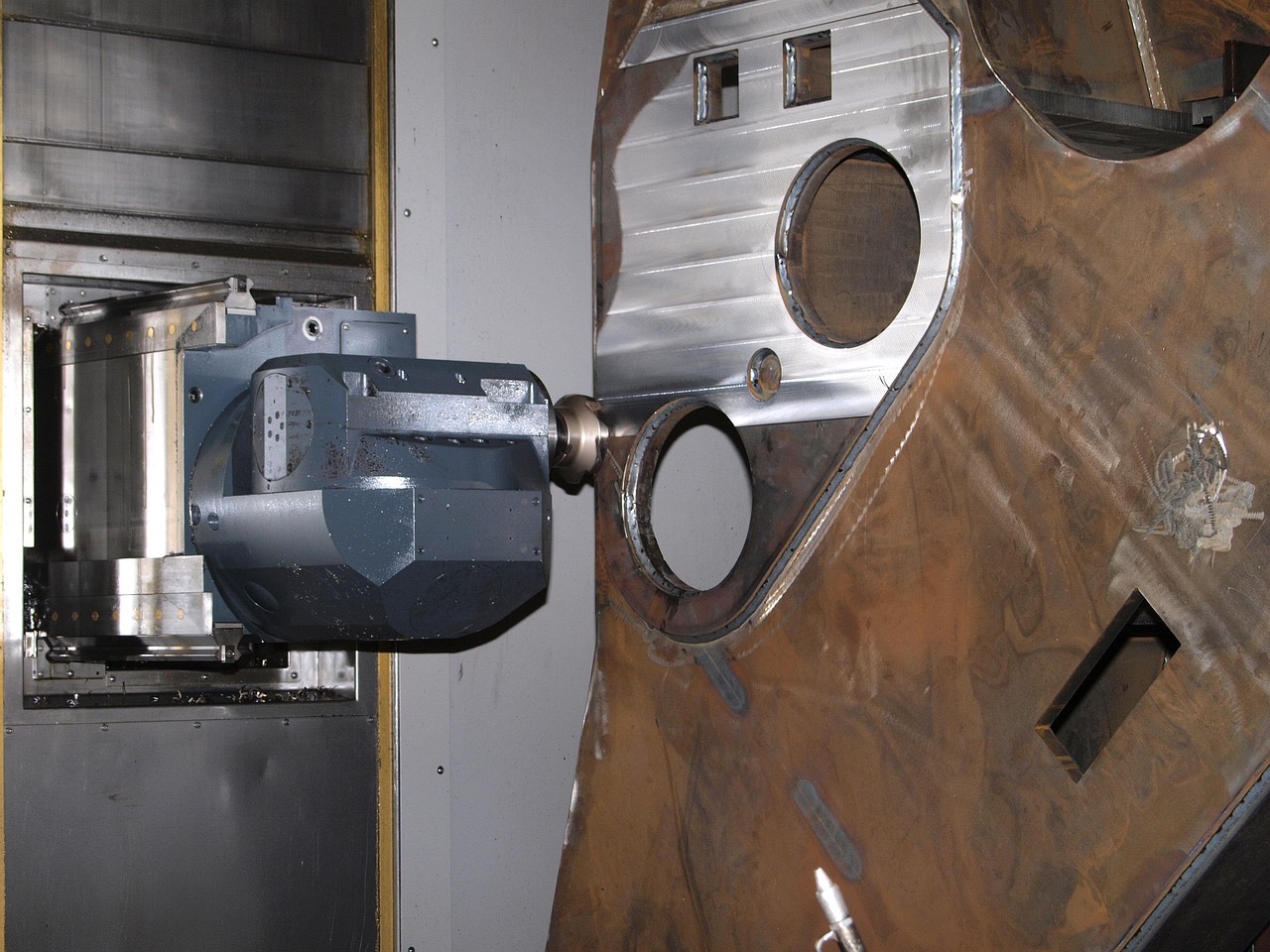
Holes placed too close to a bend line distort or tear once the metal starts stretching during forming.
As a working rule, keep holes at least 1.5 times material thickness plus the bend radius away from any bend line to avoid distortion and burring, and push slots out to three times material thickness plus bend radius, since slots concentrate stress even harder than round holes.
You can skip this spacing rule and you'll end up with oval-shaped holes wherever a feature sits too close to the fold.
Takeaway: Bend relief notches solve a related problem at corners where two bends meet. You can add a relief notch at flange edges where bends intersect, and size the relief width to match the material thickness. You can skip the relief and the corner material tears as both bends try to form at the same time.
What Should You Check Before Sending a Sheet Metal Part to Fabrication?
A design can look right in CAD and still create problems during cutting, bending, or assembly. Before releasing a part for production, run through these checks to make sure the design is manufacturable, the drawing is clear, and you're not building avoidable cost into the part.
- Material and Thickness: Check that the selected material and thickness provide the required strength, weight, corrosion resistance, and environmental performance, while also being readily available for production.
- Bend Radius and Angles: Confirm that every bend radius and angle is compatible with the material, thickness, tooling, and fabrication process. High-strength materials may require larger radii or additional consideration during forming.
- Hole and Cutout Placement: Review holes, slots, notches, and other cutouts near bends and edges. Features positioned too close to a bend can distort during forming, while features too close to an edge can weaken the part.
- Tolerance Requirements: Separate critical dimensions from general dimensions. Tight tolerances should be reserved for features that affect fit, assembly, or function rather than applied uniformly across the drawing.
- Fabrication Complexity: Look at the number of bends, setups, tooling changes, welds, and secondary operations required to produce the part. Simplifying the design where possible can reduce both production time and cost.
- Flat Pattern Accuracy: Verify that the CAD model uses the correct material thickness, bend radius, bend allowance, K-factor, and bend deduction. These inputs determine whether the flat pattern will produce the required finished dimensions.
- Drawing and File Requirements: Make sure the fabrication package clearly specifies material, thickness, dimensions, tolerances, bends, holes, finishes, and other critical requirements. Provide the appropriate CAD and drawing files for the fabrication process.
- Manufacturing Feasibility: Finally, review the complete part against the actual capabilities of the fabrication process. A design may be geometrically correct but still require unnecessary tooling, difficult setups, or secondary operations that could have been avoided earlier.
Where Wootz.work Fits Into This
At Wootz.work, we don't simply pass a drawing to a factory and wait for the parts to come back. Our engineering and quality teams work directly inside our partner factories in India, reviewing designs, checking manufacturability, and monitoring production against the requirements agreed at the start of the job.
That means we're close enough to the process to catch problems early, while remaining independent enough to challenge a production decision when a part doesn't meet spec. Our quality checks are documented, so you're not relying on a promise that a batch was inspected; there's a record of what was checked and what was delivered.
The result is a manufacturing relationship that sits somewhere between an engineering team and a traditional factory relationship. You get the cost advantages of manufacturing in India without having to manage the factory yourself, while our team stays accountable for the engineering details, quality requirements, and timelines we commit to.
If your design calls for tighter tolerances on a few specific features, we'll tell you where that precision matters and where standard fabrication tolerances are enough. The goal isn't to make every dimension tighter; it's to make sure the part you receive is the part you actually needed.
Get Your Sheet Metal Design Reviewed Before You Quote
Send us your CAD file and drawing, and our engineering team will flag bend radius, tolerance, and manufacturability issues before you commit to a production run. A free design-for-manufacturability review from Wootz.work catches costly errors early and gets your part into production faster.
Request a Free DFM ReviewFrequently Asked Questions
What is sheet metal design?
Sheet metal design means building a flat pattern and folding plan for a part that gets cut and bent from a single sheet of metal. It accounts for material thickness, bend radius, tolerance, and manufacturing limits from the first sketch, rather than treating those as an afterthought.
What is the minimum bend radius for sheet metal?
The minimum bend radius depends on material, thickness, and bend angle, but shops commonly hold it close to one times material thickness for mild steel and slightly less for soft aluminum. Many precision fabricators standardize around a 0.030 inch radius for material up to 0.125 inches thick, since that avoids custom tooling costs.
What is bend allowance in sheet metal?
Bend allowance is the length of material a bend consumes, calculated from the inside radius, material thickness, K-factor, and bend angle. It lets you work out the correct flat pattern size before the part ever reaches the press brake.
What is the K-factor in sheet metal bending?
The K-factor is the ratio that describes where the neutral axis sits within the material thickness during a bend, usually somewhere between 0.3 and 0.5. It feeds directly into the bend allowance formula and determines how accurately your flat pattern folds into its final shape.
How thick is 18-gauge sheet metal?
18-gauge steel measures about 1.21 mm, while 18-gauge aluminum measures about 1.02 mm, since gauge numbers translate to different actual thicknesses depending on material. Always check a material-specific gauge chart rather than assuming one universal figure applies.
What tolerance standard should I use for sheet metal parts?
ISO 2768 and ASME Y14.5 are the two standards most commonly referenced on sheet metal drawings, and ISO 2768-m covers general tolerances for most commercial work. Save tighter tolerances for the features that genuinely need precision, since over-specifying tolerance adds cost without adding function.
Why did my sheet metal part crack during bending?
Cracking during bending almost always comes back to a bend radius that's too small for the material's thickness and hardness, or a bend angle that concentrates too much stress in one spot. Check the minimum bend radius for your specific material before you finalize the design, and that usually solves it.
What are the basic sheet metal design guidelines?
Good sheet metal design starts with the manufacturing process, not just the finished shape. Keep bend radii appropriate for the material and thickness, maintain enough distance between holes and bends, avoid unnecessarily tight tolerances, and design features around the capabilities of the cutting, forming, and bending equipment being used.
What are the most important sheet metal design rules?
The most important sheet metal design rules are to maintain a suitable bend radius, keep holes and cutouts far enough from bend lines, account for material thickness, avoid unnecessarily complex bends, specify realistic tolerances, and use consistent bend directions where possible. These rules reduce distortion, cracking, tooling issues, and unnecessary fabrication costs.
How does sheet metal thickness affect design?
Sheet metal thickness affects bend radius, bend allowance, part stiffness, hole sizes, forming limits, weight, and fabrication cost. A thicker sheet generally requires more bending force and may require a larger inside radius, while a thinner sheet is more susceptible to distortion and deformation.
How do you choose sheet metal thickness for a part?
Choose sheet metal thickness based on the required strength, stiffness, weight, operating environment, available material grades, and fabrication process. The thinnest possible material is not always the lowest-cost option because very thin material may require additional bends, ribs, supports, or forming operations to achieve the required rigidity.
What happens if the bend radius is too small?
A bend radius that is too small can cause cracking, deformation, excessive thinning, or loss of mechanical strength around the bend. Harder materials and thicker sheets generally require more careful radius selection, so the minimum recommended radius should be checked before finalizing the design.
What is the difference between bend allowance and bend deduction?
Bend allowance is the length of material along the neutral axis that is consumed by a bend. Bend deduction is used to calculate the flat-pattern dimensions from the finished part dimensions. Both are used to accurately unfold a bent sheet metal component before cutting.
What is DFM in sheet metal design?
Design for manufacturability, or DFM, means designing a sheet metal part so that it can be produced consistently, efficiently, and at the required quality. For sheet metal, DFM considerations include material selection, thickness, bend radius, bend sequence, hole placement, tolerances, tooling access, and the number of fabrication operations.
How can I reduce the cost of a sheet metal part through design?
The biggest opportunities usually come from simplifying the geometry, reducing the number of bends and setups, using standard material thicknesses, avoiding unnecessarily tight tolerances, minimizing secondary operations, and designing holes and features around standard tooling. A manufacturable design can often reduce both production time and tooling requirements.
What is a flange in sheet metal design?
A flange is a section of sheet metal that is bent away from the main plane of the part. Flanges are commonly used to add stiffness, create mounting surfaces, join components, or form enclosures and brackets without requiring additional material.
What file format is best for sheet metal fabrication?
STEP files are commonly used for sharing 3D CAD geometry, while DXF files are widely used for 2D profiles and flat patterns for cutting operations. The preferred format depends on the fabrication process and the manufacturer's workflow, so providing the native CAD file or a production-ready STEP/DXF alongside a dimensioned drawing is often useful.
How do you prepare a sheet metal design for manufacturing?
Before sending a design to fabrication, check material and thickness, bend radii, hole-to-edge and hole-to-bend distances, bend sequence, tooling access, flat-pattern dimensions, tolerances, and surface-finish requirements. A design-for-manufacturing review can identify features that may cause fabrication problems before the part reaches production.
What is the difference between sheet metal design and sheet metal fabrication?
Sheet metal design defines the geometry, dimensions, material, bends, tolerances, and manufacturing requirements of the part. Sheet metal fabrication is the physical process of cutting, bending, forming, joining, and finishing that material to produce the designed component.
Can sheet metal design be automated?
Yes. Modern CAD systems can automate flat-pattern generation, bend calculations, bend allowances, and design-rule checks. Automated design and manufacturing workflows can also flag issues such as unsuitable bend radii, feature interference, and manufacturing constraints before production.
What materials are commonly used for sheet metal fabrication?
Common sheet metal materials include mild steel, stainless steel, aluminum, galvanized steel, and other specialty alloys. Material selection depends on strength, corrosion resistance, weight, conductivity, temperature resistance, appearance, and the forming characteristics required by the finished part.
How does material choice affect sheet metal bending?
Material choice affects springback, minimum bend radius, forming force, cracking risk, and the final accuracy of the bend. Two materials with the same nominal thickness can behave very differently during bending, so bend parameters should be based on the specific material grade rather than thickness alone.
How do you prevent springback in sheet metal bending?
Springback can be managed by selecting appropriate bend parameters, tooling, bend radius, and forming methods, with compensation applied where necessary. The amount of springback depends on material properties, thickness, bend angle, and tooling, so production settings often need to be validated with test bends.
What causes sheet metal deformation during fabrication?
Deformation can result from excessive heat, residual stress, unsuitable bend sequences, insufficient material support, aggressive forming, or cutting patterns that introduce uneven stresses. Proper feature placement, bend sequencing, material selection, and process planning can reduce unwanted distortion.

.svg)