When a product goes over budget, manufacturing is often the first place people look. But by then, most of the expensive decisions have already been made.
The shape of a part, the material it's made from, the tolerances it requires, and the way it's assembled all influence how easy, or difficult, it will be to manufacture. Design for Manufacturing (DFM) helps engineers evaluate these choices before production begins, making it possible to reduce costs, shorten lead times, and avoid unnecessary redesigns.
What Is Design for Manufacturing (DFM)?
Design for Manufacturing is the practice of designing parts and products so they are easy, fast, and cheap to produce. It means thinking about machining, tooling, assembly, and material selection while a part is still on screen, not after the first prototype fails.
The goal is simple: reduce cost and complexity without changing what the product needs to do.
DFM is closely related to Design for Assembly (DFA), which focuses specifically on how easily parts fit together during assembly. Many engineers treat DFM and DFA as a single combined practice called DFMA. Both fall under a broader umbrella called Design for Excellence (DFX), which also includes design for reliability, serviceability, and sustainability.
But there's a difference between them. DFM asks whether a part can be made efficiently. And DFA asks whether it can be put together efficiently once it exists. A part can pass one test and fail the other, which is why strong engineering teams check for both.
Why Do Manufacturing Costs Get Decided Before Production Even Begins?
This sounds counterintuitive at first. Production happens on the factory floor, so it seems like costs should be determined there too. In reality, the floor mostly executes decisions that were made much earlier.
Research on product development consistently points to the same range: somewhere between 70% and 80% of a product's total manufacturing cost gets committed during the early design stage. Design engineers choose the geometry, the material, the tolerances, and the manufacturing process. Everything downstream, including tooling, machining time, scrap rate, and assembly labor, follows from those early choices.
A tight tolerance added out of habit can force a part onto a slower, more expensive machine. An unusual material can eliminate half your supplier options overnight. A single unnecessary feature can turn a simple stamping operation into a multi-step machining job.
None of these choices look expensive on the CAD screen. They only become expensive once quoting and production start, and by then, changing them costs far more than getting them right the first time.
What Are the 10 DFM Rules That Actually Cut Production Costs?
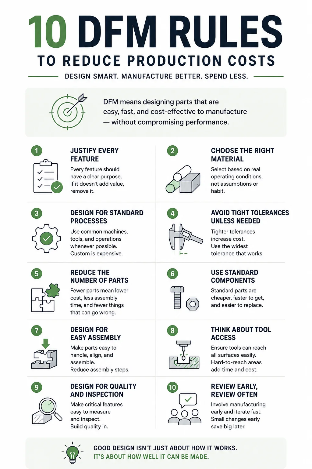
Complexity itself is not the enemy here. A satellite bracket or a surgical implant needs to be complex, and building that complexity well is the actual value a fabrication shop provides. The problem is complexity that shows up by accident, sitting in a drawing because nobody checked whether it was necessary, and gets paid for anyway.
The real discipline behind DFM is making sure every bit of complexity in a design is there on purpose, not by accident, and that its cost is understood before it reaches the shop floor. So here are a few DFM principles that are important to ensure you can optimize production costs.
1. Eliminate unnecessary features that add machining costs
Every feature on a part should trace back to a real requirement, whether that is strength, fit, airflow, or aesthetics. A feature that exists because it looked good in the CAD render, rather than because the application needed it, adds cost without adding value.
The fix is not to simplify everything by default, it is to ask what each feature is actually doing before it goes to production.
Take a mounting bracket with six decorative fillets that serve no structural purpose. Removing them might save a setup pass without changing performance at all. On the other hand, a heat exchanger with dozens of internal channels earns every one of those features because each channel does real thermal work, and that complexity is worth paying for.
Takeaway: Before releasing a design for quoting, do a feature-by-feature pass and require a functional reason for anything that survives.
2. Choose materials based on operating conditions, not on what sounds strongest
Material selection often happens early, before load cases and thermal limits are fully worked out, so engineers default to whatever material has the biggest margin. A bracket that will only ever see room temperature does not need a nickel superalloy rated for 600 degrees Celsius, even though specifying it feels safe.
This mistake runs in both directions. A part destined for a jet engine hot section genuinely needs that superalloy, and no amount of cost pressure should push a team toward a cheaper substitute that cannot survive the environment. The only reliable fix is pinning down the real operating conditions first, temperature range, load, corrosion exposure, fatigue cycles, and then letting the material follow from that data.
Takeaway: Require a documented operating envelope before a material gets locked into the drawing, not after.
3. Match the manufacturing process to your production volume
CNC machining, injection molding, casting, and sheet metal fabrication all carry very different cost structures, and the difference comes down almost entirely to tooling investment versus per-part cost. CNC machining needs no dedicated tooling, so a run of ten prototype parts is usually cheapest on a mill.
Injection molding requires a mold that can cost tens of thousands of dollars, but once that mold exists, per-part cost drops sharply, so a production run of fifty thousand units usually beats CNC by a wide margin.
Teams that design a part without knowing which side of that curve they are on end up paying for the wrong process. A part engineered for high volume injection molding, then produced in a run of five hundred units, absorbs a mold cost that never gets recovered. A part that should have moved to molding at scale, but stays on CNC out of habit, pays a machining premium on every single unit indefinitely.
Takeaway: Confirm expected production volume before finalizing process selection, and revisit that choice if the volume forecast changes.
4. Avoid unnecessarily tight tolerances
This is where the numbers matter. Manufacturing data on CNC machining shows that moving from a rough tolerance around 0.76 millimeters to a precision tolerance near 0.025 millimeters can raise machining cost by roughly four times. Pushing further, down to an ultra-precision tolerance near 0.0025 millimeters, can run as high as 24 times the standard price, since it demands slower cutting speeds, specialized fixturing, and full dimensional inspection on every part.
A single tight tolerance copied from an old drawing, sitting on a surface that never mates with anything else, can quietly double what a part costs to produce. This happens more often than most teams realize, because tolerances get inherited from previous designs without anyone rechecking whether the new part actually needs that precision. A sealing surface or a bearing seat genuinely requires tight control, since the part fails without it. A cosmetic exterior surface almost never does.
Takeaway: Review every tight tolerance on the drawing individually and ask what fails functionally if it loosens.
5. Combine parts when it reduces total cost, including the cost of repair
Fewer parts in an assembly generally means fewer manufacturing operations, fewer inspection steps, and less assembly labor.
A bracket and a mounting plate that are currently welded together as two separate pieces can often become one stamped part, removing an entire welding operation along with its inspection.
Part consolidation has a real tradeoff that gets missed often. A single complex part can be significantly harder to service in the field than two simple parts bolted together, since a worn feature on the combined part may force a technician to replace the entire assembly instead of one small component.
The right call depends on how the product actually gets maintained over its working life, not just what looks cheapest to manufacture on the first production run.
Takeaway: Before consolidating parts, check the service and maintenance plan for the product, not just the manufacturing cost estimate.
6. Standardize components and fasteners
Five different fastener types on one assembly create five separate purchase orders, five inventory lines, and five opportunities for the wrong part to end up on the line. Reducing that down to one or two standard fastener sizes is a low-risk, high-value change, and it also increases purchasing leverage since order volume concentrates on fewer part numbers.
The exception is a fastener chosen for a documented reason, a specific torque rating, vibration resistance, or corrosion performance that a standard part cannot match. That fastener stays as specified.
Everything else on the bill of materials should default to a standard part unless someone can point to a functional requirement that says otherwise.
Takeaway: Audit the fastener list on every new design and flag any non-standard part for justification before release.
7. Design for faster, error-free assembly
An asymmetric key on a connector prevents it from being installed backward, removing the error entirely instead of relying on an assembly worker to catch it. This approach, often called poka-yoke in manufacturing, comes out of Japanese lean production practice and works because it eliminates the mistake at the design stage rather than catching it during inspection after the fact.
This matters more as assemblies grow in size and part count. A two-piece bracket has very few ways to go together wrong, and mistake-proofing it barely matters. A fifty-part sub-assembly has dozens of possible failure points, and every one of them costs real money in rework if it gets missed on the line.
Takeaway: For any assembly with more than a handful of parts, review each mating interface for a way to make incorrect assembly physically impossible.
8. Design features that are easy to machine
A deep internal pocket or an angled thread can look completely reasonable on a screen and be extremely difficult, or impossible, for a standard tool to cut. This gap between CAD geometry and actual tool access is one of the most common and most expensive surprises in manufacturing, and it usually only surfaces once a machinist starts programming toolpaths for the part.
Some geometry genuinely needs the extra setup or specialized tooling this requires, because the application demands that exact feature. The failure is not designing something difficult to machine. It is not knowing in advance, so the added cost and lead time show up as a shock in the quote instead of a planned line item in the budget.
Takeaway: Run a manufacturability check on any internal or hard-to-reach feature before finalizing the design, ideally with input from whoever will actually machine the part.
9. Design for faster inspection and quality control
A dimension that cannot be measured reliably cannot be verified, and a dimension that cannot be verified will eventually cause a quality problem downstream. Critical features need to be accessible to standard measuring tools wherever the application allows it, calipers, gauges, or a coordinate measuring machine, so inspection stays fast and repeatable.
This matters even more in regulated industries like aerospace and medical devices, where every critical dimension needs a documented, traceable inspection record. Some parts will always require specialized inspection methods, such as CT scanning for internal geometry that cannot be reached any other way.
That cost is legitimate and should be planned for from the start, rather than discovered as a surprise during final quality checks.
Takeaway: For every critical dimension on the drawing, confirm which inspection method will verify it before the part goes into production.
10. Bring manufacturing into the design process early
The most expensive DFM failure is treating manufacturability review as a single checkpoint right before production starts. By that point, tooling decisions, material choices, and geometry are already locked in, and any change discovered during that final review is expensive and slow to implement. Manufacturability should get reviewed at the concept stage, again as the CAD model firms up, and again once the first prototype comes back from the shop.
Each of these reviews catches different problems. A concept-stage review catches process and material mismatches early, when changing them costs almost nothing. A CAD-stage review catches tolerance and tool access issues before tooling gets ordered. A prototype-stage review catches the problems that never show up on a screen, like assembly friction or a feature that machines differently than expected.
Takeaway: Schedule manufacturability review as three separate checkpoints across the design timeline, not one review at the end.
What Should a DFM Design Review Checklist Include?

A structured checklist keeps DFM consistent and ensures your production conditions are factored in deliberately and proactively. Here is a practical starting point for engineering teams to use before releasing a design for quoting.
| Review area | Questions to ask |
|---|---|
| Geometry | Can every feature be justified functionally? |
| Material | Is the material available from more than one supplier? |
| Process | Does the design fit a standard, widely available manufacturing process? |
| Tolerances | Are tight tolerances limited to only fit and function-critical dimensions? |
| Part count | Can any parts be combined or eliminated? |
| Fasteners | Are fasteners and hardware standardized across the assembly? |
| Assembly | Can the part only be assembled correctly? |
| Tool access | Can every feature be reached by standard tooling? |
| Inspection | Can critical dimensions be measured with standard equipment? |
| Timing | Has manufacturing been consulted before this stage? |
How Does DFM Reduce Costs Across the Entire Product Lifecycle?
DFM is often framed purely as a cost-cutting exercise for the production floor. Its real impact stretches across the entire product lifecycle, from the first quote to long-term maintenance.
During quoting, a manufacturable design gets more competitive bids because more suppliers can actually build it. During tooling, simpler geometry means cheaper molds, fixtures, and dies. During procurement, standardized materials and components mean shorter lead times and fewer single-source risks.
During production, fewer tight tolerances mean faster cycle times and higher first-pass yield. During quality inspection, accessible features mean faster checks and fewer false rejects. During assembly, mistake-proof design means fewer errors and less rework on the line.
Even maintenance benefits from good DFM decisions made years earlier. Standard fasteners and accessible components make field repairs faster and cheaper. A product designed with manufacturing in mind at the start tends to stay cheaper to support for its entire life.
When Should a DFM Review Happen?
The honest answer is throughout, not once. DFM works best as a continuous check rather than a single gate near the end of development.
- Concept stage: Rough sketches and early CAD models get reviewed for major red flags, like unusual processes or materials that would limit supplier options later.
- Detailed CAD stage: Full drawings get checked feature by feature against the checklist above, catching tolerance and geometry issues while changes are still cheap.
- Prototype stage: The first physical parts reveal problems that never show up on screen, like tool access issues or assembly friction that CAD software cannot fully simulate.
- Pilot production stage: Small batch runs test whether the design holds up at slightly higher volume, surfacing issues with repeatability and process capability.
- Mass production stage: By this point, DFM should already be locked in. Any changes made here are the most expensive changes possible, since tooling, supply chains, and quality systems are already committed.
The earlier a manufacturability problem gets caught, the cheaper it is to fix. A change made on a CAD screen costs almost nothing. The same change made after tooling is cut can cost thousands of dollars and weeks of delay.
Not Sure If Your Design Is Ready for Production?
A small design change can eliminate unnecessary machining, reduce assembly time, or avoid expensive tooling changes. Wootz.work works with engineering teams to identify manufacturability issues early, helping you reduce production costs while improving quality and scalability.
Talk to Our Manufacturing ExpertsFrequently Asked Questions
What is the main goal of Design for Manufacturing (DFM)?
The primary goal of Design for Manufacturing (DFM) is to reduce production costs and improve manufacturability by considering manufacturing requirements during the product design stage. Instead of treating manufacturing as the final step, DFM encourages engineers to evaluate how design decisions, like material selection, part geometry, tolerances, and manufacturing processes, will affect production. A well-executed DFM process helps reduce material waste, simplify machining and assembly, shorten production lead times, improve product quality, and minimize costly engineering changes later in the product lifecycle.
What is meant by Design for Manufacturing?
Design for Manufacturing (DFM) is an engineering methodology that optimizes a product's design so it can be manufactured efficiently, consistently, and at the lowest practical cost. It involves designing parts that are easier to produce using available manufacturing processes while maintaining the required functionality, quality, and reliability. Rather than asking, "Can this part be made?", DFM asks, "Can this part be made economically and repeatedly at scale?"
How is DFM different from DFA?
Although they're often used together, Design for Manufacturing (DFM) and Design for Assembly (DFA) solve different problems. DFM focuses on making individual parts easier and less expensive to manufacture by optimizing factors such as material choice, geometry, tolerances, and manufacturing processes. DFA, on the other hand, focuses on making the final product easier to assemble by reducing part count, simplifying fastening methods, improving accessibility, and minimizing assembly time. Together, they form Design for Manufacturing and Assembly (DFMA), a methodology that optimizes both production and assembly to reduce overall product costs.
What is an example of Design for Manufacturing?
Imagine a product housing designed with ten custom screws, multiple tight tolerances, and complex internal pockets that require several machining operations. A DFM review might recommend replacing the custom screws with standard fasteners, relaxing non-critical tolerances, simplifying the internal geometry, and redesigning features to be manufactured in fewer machining setups. These relatively small design changes can reduce machining time, tooling costs, assembly effort, and inspection requirements without affecting the product's performance.
What is the Design for Manufacturing method?
The DFM method is a structured process used to evaluate whether a product design can be manufactured efficiently. While the exact approach varies by company, it generally includes selecting the most suitable manufacturing process, choosing cost-effective and readily available materials, simplifying part geometry wherever possible, applying realistic tolerances, reducing unnecessary features and components, standardizing parts and fasteners, and reviewing manufacturability with design and manufacturing teams before production. The objective is to identify potential manufacturing challenges early, when design changes are faster and less expensive to implement.
How much can DFM reduce manufacturing costs?
The exact savings vary depending on the product, production volume, and manufacturing process. That means improving manufacturability early often has a much greater impact than trying to reduce costs after production begins. In practice, effective DFM can lower material usage, reduce machining and assembly time, minimize scrap and rework, shorten lead times, and decrease tooling costs.
What does a DFM engineer do?
A DFM engineer evaluates product designs before production to identify opportunities to improve manufacturability and reduce costs. They work closely with product designers, manufacturing engineers, suppliers, and quality teams to ensure products can be produced efficiently and consistently. Typical responsibilities include reviewing CAD models, recommending material or process changes, analyzing tolerances, identifying manufacturing risks, conducting DFM reviews, and helping optimize production workflows before tooling or mass production begins.
When should manufacturing be involved in the design process?
Manufacturing teams should be involved as early as the concept and preliminary design stages. Waiting until the design is finalized often results in expensive engineering changes, tooling modifications, or production delays. Early collaboration allows manufacturing constraints to influence design decisions before they become difficult or costly to change, resulting in faster product development and fewer production issues.
Is Design for Manufacturing a skill?
Yes. Design for Manufacturing is considered one of the core skills for product designers, mechanical engineers, manufacturing engineers, and industrial designers. It combines knowledge of manufacturing processes, materials, tolerances, production economics, quality control, and engineering design. Strong DFM skills enable engineers to design products that are not only functional but also practical and cost-effective to manufacture at scale.
What comes first, DFMEA or PFMEA?
Design Failure Mode and Effects Analysis (DFMEA) comes first because it evaluates potential failures in the product design before manufacturing begins. Once the design is finalized, Process Failure Mode and Effects Analysis (PFMEA) identifies potential failures that could occur during manufacturing and assembly. In other words, DFMEA focuses on design risks, while PFMEA focuses on manufacturing process risks. Together, they help improve product quality throughout development and production.
What is DFS in manufacturing?
DFS usually stands for Design for Serviceability (sometimes called Design for Service). It focuses on designing products so they are easier to inspect, maintain, repair, or replace throughout their service life. While DFM reduces manufacturing costs, DFS reduces maintenance costs by improving accessibility, simplifying component replacement, and minimizing downtime after the product reaches the customer.
What is a DFM checklist?
A DFM checklist is a structured review used to evaluate whether a product is ready for efficient manufacturing. It helps engineering teams identify potential cost drivers and manufacturing challenges before production begins. A typical DFM checklist asks: Is the selected material suitable and readily available? Can the part geometry be simplified? Are tolerances no tighter than necessary? Are standard components and fasteners used wherever possible? Does the design minimize machining, tooling, and assembly complexity? Can the product be inspected easily? Has the design been reviewed with manufacturing engineers? Using a DFM checklist before prototyping or tooling helps reduce engineering changes, improve production efficiency, and lower overall manufacturing costs.
What are the principles of Design for Manufacturing?
The core principles of Design for Manufacturing are simplicity, standardization, process compatibility, material optimization, realistic tolerances, ease of assembly, and early collaboration between design and manufacturing teams. Together, these principles help reduce production costs, improve product quality, shorten lead times, and make manufacturing more consistent at scale.

.svg)