Most people associate CNC machining with what happens on the shop floor, but the process really begins much earlier.
By the time a part reaches the machine, many of the decisions that influence manufacturing efficiency have already been made in the CAD model. Wall thickness, internal corners, hole depths, and tolerance specifications all play a role in how easily a part can be machined, how long production takes, and what it ultimately costs.
The good news is that designing for CNC machining doesn't mean compromising on performance. It means understanding how machining works and making design choices that help manufacturers produce your parts accurately and efficiently.
What Is Custom CNC Machining, Really?
CNC stands for Computer Numerical Control. In simple terms, it means a machine reads a digital program and uses cutting tools to remove material from a solid block until you have the shape you want.
The two most common CNC processes are:
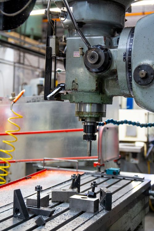
- Milling (where the tool rotates and moves across a stationary or rotating part)
- Turning (where the part itself spins and a cutting tool shapes it)
What makes it custom is that every part is machined to a specific design file, usually a 3D CAD model in STEP or IGES format, rather than following a standard catalog shape. You're not ordering off the shelf but telling the machine exactly what to make.
Custom CNC machining is used across:
- Aerospace
- Automotive
- Medical devices
- Electronics
- Industrial equipment
- Consumer products
It works for both one-off prototypes and high-volume production runs. It handles metals and plastics. And it produces parts with dimensional accuracy that most other manufacturing processes can't match.
That said, CNC machining has real constraints. Knowing them before you design saves significant time and money.
Where Should You Start the Design Process?
There are different ways to start the design process for custom CNC machining. But most often, it needs to start with the design's purpose and the part.
Start With Function, Not Geometry
The first question is not "how do I model this?" It's "what does this part need to do, and what does it need to fit with?"
What loads or forces will the part handle?
A bracket that holds a small sensor needs different wall thicknesses than one that supports a hydraulic actuator. If the part is structural, your design will be driven by stress and deflection requirements, not just shape.
What does it need to interface with?
Mating surfaces, threaded holes, press fits, and alignment features all have tolerance requirements. Define those early, so they drive the design, not the other way around.
What environment will it operate in?
Temperature cycling, corrosion exposure, electrical insulation needs, and surface contact requirements all affect your material choice, which in turn affects your design.
These answers can help shape every decision you make downstream.
How Do You Choose the Right Material?
There are different metals to choose from for custom CNC machining, but here are some of the most common ones to consider:
Metals
Aluminum alloys
Aluminum alloys (6061 and 7075 in particular) are the most commonly machined metals. They cut fast, hold tight tolerances well, and are cost-effective for both prototyping and production. 6061-T6 is general-purpose and welds easily. 7075-T6 is stronger but less corrosion-resistant and harder to anodize.
If your part needs light weight plus structural strength, aluminum is almost always the right starting point.
Stainless steel
Stainless steel (most commonly 303 and 316) is chosen when corrosion resistance or food-grade compliance is required. It's harder to machine than aluminum, which means slower feeds, more tool wear, and higher cost. But it's the right choice for marine, medical, or chemical environments. 316 has better corrosion resistance than 303; 303 machines more easily.
Mild steel
Mild steel (like 1018 or A36) is strong, cheap, and widely used for structural parts where weight isn't a concern. It's not naturally corrosion-resistant, so it typically needs a surface treatment.
Titanium
Titanium (grade 5, also called Ti-6Al-4V) is used when you need a high strength-to-weight ratio and good corrosion resistance in a demanding environment. Aerospace and medical implants are the main applications. It's difficult and expensive to machine, so it's not a casual choice.
Other metals
- Brass machines extremely well and is used for fluid fittings, electrical connectors, and decorative parts.
- Copper is used for its electrical and thermal conductivity.
- Tool steels such as H13 or D2 are used when the machined part itself needs to be hard and wear-resistant.
Plastics
Delrin (POM/acetal)
Delrin is the go-to plastic for precision machined parts. It's dimensionally stable, low friction, and machines cleanly to tight tolerances. Bearings, bushings, and valve components are common applications.
Nylon
Nylon is tougher and more impact-resistant than Delrin but absorbs moisture, which can cause dimensional change. It's used in gears, rollers, and structural brackets.
PEEK (polyether ether ketone)
PEEK is high-performance and expensive. It maintains its properties at elevated temperatures and in aggressive chemical environments. It's used in medical devices and aerospace components where metals are too heavy.
Polycarbonate and acrylic (PMMA)
Polycarbonate and acrylic are used when optical clarity or visual inspection through the part is needed. Acrylic is more brittle; polycarbonate is tougher but scratches more easily.
PTFE (Teflon)
PTFE is extremely low-friction and chemically inert, but it's soft and difficult to hold to tight tolerances. It's used for seals, liners, and non-stick surfaces.
What should drive your choice?
A simple way to think about it: start with aluminum for custom CNC machining unless you have a specific reason not to. If the application demands corrosion resistance, go with stainless steel. If it requires high-temperature or chemical resistance in a non-metallic form, consider PEEK. If you need low friction without lubrication, Delrin is usually your answer.
Another thing to keep in mind is that machinability directly affects cost. Aluminum is roughly three to four times as fast to machine as stainless steel. That difference shows up in your quote.
Tolerances: tighter is not always better
Tolerances define how much a dimension is allowed to vary from its nominal value. A tolerance of ±0.13 mm (about ±0.005 in.) is considered standard for most custom CNC machined parts and is achievable across a wide range of materials and machine types.
For applications that need tighter control, like in aerospace components, press fits, precision assemblies, tolerances of ±0.025 mm (±0.001 in.) or better are achievable in metals. But they require more time, more passes, and often 100% inspection of the finished parts.
The practical rule is: specify the tolerance your design actually needs, not the tightest one you can imagine. Every time you tighten a tolerance, cost goes up. Surfaces that need to be inspected against a tight callout require measurement time. Features that approach the limits of the machine's capability require extra care from the operator.
For most non-critical dimensions, a general tolerance grade is fine. If you don't call out tolerances on your drawing, most shops will default to ISO 2768 medium, which is around ±0.1 mm for dimensions up to 30 mm.
Internal corners: they will always have a radius
This is the most misunderstood constraint in custom CNC design. When a milling tool cuts into a pocket or cavity, it leaves a radius in every internal corner. The minimum radius equals the tool radius. You cannot cut a perfectly sharp internal corner with a standard mill.
A good working rule is to design your internal corner radii to be at least one-third of the cavity depth. So if a pocket is 30 mm deep, your internal vertical corner radius should be at least 10 mm. A slightly larger radius (say, 130% of the tool's radius rather than exactly equal) will actually improve surface finish because it lets the tool follow a smooth arc rather than a hard stop.
If you genuinely need a 90-degree internal corner for a mating part that has square edges, for example, there are two ways to handle it: a dog-bone corner (small circular cutout at each corner that gives a mating square part room to fit), or EDM (Electrical Discharge Machining), which can produce true square corners but at significantly higher cost and longer lead time.
Cavity depth: the 4:1 rule
End mill tools have a limited cutting length, typically three to four times their diameter. When a cavity is deeper than about four times its width, you run into problems: the tool deflects, chips don't evacuate cleanly, and vibration degrades the surface finish and dimensional accuracy.
The guideline used by most experienced machinists and design-for-manufacturing resources is to keep cavity depth at no more than four times the cavity width. If your design needs a deeper pocket, consider splitting the part, machining from multiple sides, or using a variable-depth profile to reduce the effective depth.
Wall thickness: don't go thinner than you need to
Thin walls flex and vibrate during machining. That vibration is the enemy of accuracy and surface finish. It also creates heat that can cause dimensional changes, especially in plastics.
The minimum recommended wall thickness is 0.8 mm for metals and 1.5 mm for plastics. These are practical minimums, not targets. For most structural parts, you'll want considerably more. A useful ratio to keep in mind: wall height should be no more than 10 times the wall thickness. A 2 mm thick wall standing 20 mm tall is at the edge of what's feasible; a 2 mm wall standing 40 mm tall is asking for trouble.
If your design genuinely requires thin features, sheet metal fabrication may be a better process than CNC machining for those sections.
Holes: use standard sizes wherever possible
Holes drilled to standard diameter sizes (M3, M4, M5 and so on for threaded holes; standard drill sizes for clearance and press-fit holes) are faster to produce and less expensive than non-standard diameters. For holes that require tight tolerances, they're typically finish-bored or reamed after drilling, which allows a diameter accuracy of ±0.013 mm or better.
Keep hole depth reasonable. Deep holes require specialized drills, slower feeds, and more frequent chip clearing. If you're designing a blind threaded hole, a common mistake is making it exactly as deep as the thread engagement length. Always leave extra depth below the threads for the tap to run out cleanly.
Avoid flat-bottomed holes unless they're genuinely required. Standard drill tips produce a conical bottom. Creating a flat bottom requires a secondary operation with an end mill.
How Do You Get Your File Ready for Quoting?
Most CNC shops and online machining services accept STEP (.stp or .step) files as the primary 3D format. STEP is a neutral format that transfers geometry cleanly between CAD systems without the compatibility issues that can affect proprietary formats.
Along with the 3D file, you should provide a 2D technical drawing if your part has any critical dimensions or tolerances that the 3D model does not convey. The drawing is where you call out:
- Tight tolerances on specific features
- Surface finish requirements (Ra values, the roughness average)
- Thread callouts and engagement depths
- Material specification and heat treatment if required
- Surface treatment: anodizing, plating, passivation, powder coating, etc.
If you don't provide a drawing, most shops will machine the 3D model geometry with a general tolerance grade. That's fine for prototype parts and non-critical features, but it means you're relying on the shop to make reasonable assumptions about anything you haven't specified.
One important note: remove all unnecessary cosmetic features from your file before submitting. Chamfers and fillets that are purely decorative add machining time. If a feature isn't functional, consider leaving it out or specifying it as optional.
What About Surface Finishes?
The as-machined surface finish is what you get straight off the machine. On milled aluminum, the typical Ra is 1.6–3.2 µm. Turned surfaces are often smoother. If you need a specific finish, specify it to the CNC machining service provider.
Common surface treatments for CNC machined parts
Anodising
Anodizing is almost always used for aluminum parts. It creates a hard, corrosion-resistant oxide layer on the surface. Type II anodizing (standard) produces a layer around 5–25 µm thick and can be dyed. Type III (hard anodizing) gives a thicker, harder layer of 25–50 µm and is used for wear surfaces. Anodizing slightly changes the part dimensions, so account for the layer thickness in any tight-tolerance features before anodizing.
Bead blasting
Bead blasting gives a uniform matte texture that hides tool marks and looks clean. It's often used before anodizing or as a standalone finish. It doesn't change dimensions measurably.
Black oxide
Black oxide on steel forms a thin conversion coating that provides mild corrosion resistance and reduces glare. It doesn't add meaningful dimensional change.
Zinc or nickel plating
Zinc or nickel plating for steel parts adds corrosion protection and can improve wear resistance. Plating adds a defined layer thickness that must be accounted for on tight-tolerance features.
Passivation
Passivation for stainless steel removes free iron from the surface, improving corrosion resistance without changing appearance or dimensions.
How Do CNC Milling and Turning Differ in Design Terms?
Most people associate custom CNC machining with milling. But many parts, particularly cylindrical and rotational components, are better suited to turning, and the design rules differ.
CNC turning
In CNC turning, the part rotates against a stationary cutting tool. This makes it ideal for shafts, bushings, threaded fasteners, fittings, nozzles, and any part that's primarily cylindrical. Standard tolerances in CNC turning are similar to milling, better on critical diameters.
Threads for turned parts are typically cut using a single-point threading tool (for external threads) or taps (for internal threads). Protolabs' turning guidelines, for example, support UNC/UNF threads from #2 up to ½ inch, and metric threads from M2 to M12. If your application needs threads outside that range, confirm with the shop before designing.
Modern CNC lathes and live tooling
Modern CNC lathes also have "live tooling," which is rotating milling tools that can cut flats, keyways, cross-holes, and slots on a turned part without removing it from the machine. This dramatically expands what a turning center can produce. But there are limits: most live tooling operations support only holes perpendicular or parallel to the rotational axis. Off-angle holes usually require a milling setup.
When a part has both rotational and prismatic features, you need to decide whether it's primarily a turned part with milled features, or a milled part with turned features. This affects fixturing, setup cost, and lead time.
What Are the Most Common Mistakes in Custom CNC Designing?
After years of seeing parts come back for redesign, a few patterns repeat themselves.
Overspecifying tolerances
Calling ±0.01 mm on every dimension significantly inflates cost for no functional reason. Tolerance callouts should be reserved for features where the tolerance genuinely affects fit, function, or assembly.
Designing sharp internal corners
Every sharp internal corner in a milled pocket will need to be redesigned or handled with a dog-bone cutout. It's better to add the fillet yourself so you control its size.
Ignoring access
Designing deep pockets without regard to whether a tool can reach the bottom at the required diameter. If a feature requires a tool longer than four times its diameter, the design needs to change.
Forgetting the direction of machining
CNC milling machines cut from above. If your design has features that can only be reached from an unusual angle, like a deep undercut or a hole on the underside of an overhang, it requires either a 5-axis machine, additional setups, or a design change. Each additional setup adds cost.
Choosing material for the wrong reason
Using titanium because it sounds impressive, or 316 stainless when 6061 aluminum with anodizing would perform equally well and cost a fraction of the price. Material selection should follow the engineering requirements, not the spec sheet.
Designing to a CAD model without a drawing
For anything beyond a simple, non-critical part, the 3D model alone is insufficient. Without a drawing, there is no formal record of what surface finish was required, what tolerance applies to critical features, or what material condition is expected.
How Do You Reduce Cost Without Compromising Quality?
Cost in custom CNC machining is fundamentally driven by machining time. The more time the machine runs, the more the part costs.
- Simplify geometry: Every additional setup, every tight-radius pocket, every undercut adds time. If a feature isn't doing structural or functional work, question whether it belongs.
- Use standard hole and thread sizes; non-standard diameters require end milling rather than drilling, which is slower. Standard thread sizes are in every shop's tooling inventory; unusual ones may require ordering.
- Relax tolerances where you can: Standard tolerances (ISO 2768 medium or fine) are sufficient for most features on most parts. Reserve tight callouts for the surfaces that actually need them.
- Design for single-setup machining if possible: Every time a part is repositioned in the machine, it adds setup time and introduces potential for alignment error. If your part's features can be accessed from one or two directions, it's much cheaper to produce than one that needs five-axis or six-sided machining.
- Order in batches: Setup costs are fixed. Whether you're making 1 part or 50, the setup happens once. Per-unit cost drops significantly at higher quantities.
- Match material to application: If aluminum meets the requirements, there's no reason to machine in stainless steel. Machinability differences are substantial, and they show up in cost.
What Should You Look for in a Partner Providing CNC Machining Services?
Custom machining is a relationship as much as a transaction. A shop that communicates problems early saves you significantly more than one that machines exactly what you sent and ships you parts that don't work.
Look for shops that provide DFM (Design for Manufacturability) feedback on your files
This means someone reviews your design and flags features that could cause problems before they do. Online machining platforms like Protolabs and Hubs (formerly 3D Hubs) offer automated DFM analysis when you upload a file, which is useful for quick checks.
Ask about quality documentation
For production parts, you want dimensional reports, either first-article inspection (FAI) for the first piece off the machine or incoming inspection reports. For critical applications in aerospace, automotive, or medical, shops should be able to provide material certs and traceability.
Check whether the shop's capabilities match your part
A shop set up for 3-axis aluminum milling may not be the right partner for a complex 5-axis titanium part.
Finally, ask about communication on tolerances and inspection
If you call out ±0.025 mm on a bore diameter, the shop should confirm they can hold it and have the inspection equipment to verify it.
The Bigger Picture
Custom CNC machining rewards designers who understand the process. The more you know about how the machine moves, how tools behave, and where the real cost drivers are, the better your designs will be, and the fewer surprises you'll face between the first quote and the final delivery.
Start with function. Choose your material based on engineering requirements. Design with tool geometry in mind. Specify tolerances where they matter, and leave everything else at standard. Get feedback on your design before you send it to a shop.
Most of all, treat the first prototype as a learning exercise. CNC machining is flexible enough that you can refine a design quickly. Use that flexibility. A part that costs slightly more to iterate in the early stages is far cheaper than a design that reaches production with a fundamental flaw.
Frequently Asked Questions
.svg)


