CNC machining is known for producing highly accurate components, often with tolerances that run into microns. Yet, even when a part is machined to the correct dimensions, it may not stay that way.
A flat aluminium plate can develop a slight bow, a thin-walled component can twist, or a precision-machined housing can lose its alignment after being removed from the fixture.
This is called machining distortion or warping, and it's one of the more frustrating problems manufacturers encounter, particularly when working with large, thin, or geometrically complex components.
The tricky part is that warping doesn't always happen while the machine is cutting. Sometimes, the component looks perfectly fine during production but begins to deform after unclamping, cooling, or even during subsequent machining operations. This makes it difficult to identify the actual cause, especially when the part has already passed its initial dimensional inspection.
So, why do CNC machined parts warp? The answer usually comes down to a combination of internal material stresses, heat generation, cutting forces, workholding methods, and part geometry. Understanding how these factors interact is essential to preventing distortion and maintaining dimensional accuracy throughout production.
Let's look at what causes CNC machining distortion, how different materials respond, and what manufacturers can do through better machining strategies and design decisions to keep parts dimensionally stable.
What Is Warping in CNC Machining?
Warping in CNC machining refers to an unintended change in the shape or geometry of a component during or after material removal. It can appear as bending, twisting, bowing, cupping, or a change in flatness.
Machining distortion can result from the redistribution of residual stresses already present in the raw material, as well as new stresses introduced during cutting. Removing material changes the component's stress balance, while cutting forces and heat can further affect its shape. When material is removed, the remaining structure must redistribute those stresses. If the redistribution is uneven, the component can deform.
For example, imagine machining a thick aluminium plate into a thinner component with several deep pockets. The plate may initially be flat, but as material is removed from one side, the internal stress balance changes. Once the part is released from its fixture, it may develop a slight curve or bow.
This is particularly common in thin-walled CNC-machined parts, large aluminium plates, precision housings, and components with uneven material removal.
How Is Warping Different from Bending and Other Types of Machining Distortion?
These terms are often used interchangeably, but they describe slightly different behaviours.
- Warping: A general term for an unintended change in the shape of a component, often involving uneven deformation across its surface.
- Bending: A component curves along one direction, usually because of uneven stresses or applied forces.
- Twisting: Different sections of the component rotate relative to one another, causing the geometry to become distorted.
- Cupping: A flat surface develops a concave or convex shape, often seen in plates and sheet-like components.
- Springback: A component partially returns towards its original shape after the removal of an external force, such as clamping or forming pressure.
- Dimensional drift: Measurements change over time or with temperature, even when the component does not show obvious visible deformation.
Understanding the type of distortion matters because each one can have a different cause and may require a different corrective approach.
Why Do CNC Machined Parts Warp? 7 Common Causes
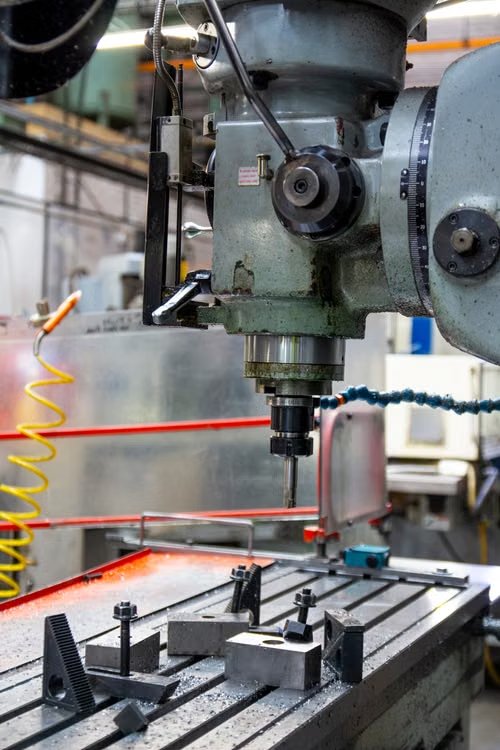
CNC machining distortion rarely comes down to one isolated issue. In most cases, several factors contribute to the final deformation, and the effect becomes more noticeable as more material is removed.
Here are seven of the most common causes.
1. Residual Stress Inside the Raw Material
Residual stress is one of the biggest reasons CNC-machined parts warp, particularly when working with aluminium alloys and other materials that have undergone extensive rolling, extrusion, forging, or heat treatment.
But what exactly is residual stress?
During manufacturing, materials are exposed to different forces, temperatures, and cooling rates. These processes can leave behind internal stresses even when the material is not being subjected to any external load.
For example, a thick aluminium plate may contain residual stresses introduced during rolling, stretching, or heat treatment, particularly quenching. These stresses can vary across the plate's thickness and length, depending on the alloy and how the material was processed.
When the plate is machined, material is removed and the original stress balance changes. The remaining material redistributes these internal stresses, which can cause the component to bend or twist.
This is why a component can begin warping even when the CNC machine, cutting tools, and machining parameters are all working correctly.
How to prevent it: Start with material that has a suitable stress-relieved or stabilised condition for the application. For components requiring significant material removal, manufacturers can use staged roughing, intermediate stress-relief treatments where appropriate, and finishing passes after the material has stabilised.
The important point is that machining cannot always compensate for stresses already present in the raw material. Material condition needs to be considered before production begins.
2. Uneven Material Removal
The way material is removed during CNC machining has a direct influence on dimensional stability.
When a component is machined heavily on one side while the other side remains relatively untouched, the internal stress distribution can become unbalanced. The component may then bend towards one side or develop a curved surface.
This is particularly noticeable when machining large plates, pockets, cavities, and components with different wall thicknesses.
For example, imagine a rectangular aluminium block being machined into a housing. If one side is completely pocketed out while the opposite side remains thick, the remaining material may respond differently as internal stresses are released.
The problem can become more pronounced during rough machining, where large amounts of material are removed quickly.
How to prevent it: Distribute material removal as evenly as the geometry allows. Where possible, machine opposing faces in stages rather than completing one side entirely before moving to the other. Use balanced roughing strategies and leave a suitable machining allowance for the finishing operation.
This helps reduce sudden changes in the internal stress distribution and gives the material an opportunity to stabilise between operations.
3. Heat Generation During CNC Machining
CNC machining generates heat through friction and deformation at the cutting zone. The cutting tool interacts with the workpiece, creating heat as material is sheared away and chips are formed.
Although much of this heat is carried away by the chips and cutting fluid, some enters the workpiece.
The problem is that materials expand when heated and contract as they cool. If different areas of a component experience different temperatures, they may expand or contract unevenly.
This can lead to thermal distortion, particularly in thin-walled components and precision-machined parts where even a small dimensional change can affect assembly.
For example, a thin aluminium component may heat up during a prolonged machining cycle. If one section becomes significantly warmer than another, the resulting thermal expansion can temporarily change its geometry. Once the part cools, it may not return to exactly the same shape if other stresses have also been redistributed.
Thermal distortion becomes a greater concern when cutting conditions generate substantial heat, when heat is concentrated near the cutting zone, or when the workpiece cannot dissipate that heat effectively. The risk depends on the material, tool geometry, cutting parameters and coolant delivery.
How to prevent it: Use appropriate cutting speeds, feed rates, tool geometry, and coolant delivery to manage heat generation. Sharp tools help reduce unnecessary friction, while suitable coolant application helps control temperature at the cutting zone.
Manufacturers should also consider the temperature of the component during inspection. A part measured immediately after machining may give different readings from the same part after reaching a stable temperature.
4. Excessive Cutting Forces and Tool Pressure
During CNC machining, the cutting tool applies forces to the workpiece as it removes material. These forces depend on factors such as feed rate, depth of cut, tool geometry, material hardness, and cutting conditions.
When the forces become too high, a component can deflect during machining.
This is particularly problematic with thin sections, long unsupported components, and parts with limited structural rigidity.
Consider a long aluminium component being milled along one edge. If the workpiece is not adequately supported, the cutting force can push it away from the tool. The machine may still follow the programmed toolpath, but the material itself moves slightly during cutting.
Once the cutting force is removed, the component may spring back. The resulting part can have incorrect dimensions even though the machine has followed the programmed coordinates accurately.
This is known as machining deflection.
Excessive cutting forces can also contribute to vibration and chatter, affecting surface finish and dimensional consistency.
How to prevent it: Optimise the cutting parameters rather than simply increasing the material removal rate. Use suitable tool diameters, cutting depths, and feed rates for the material and geometry. Where necessary, use additional support and select machining strategies that reduce radial cutting forces.
The goal is to maintain stable cutting conditions without unnecessarily loading the component.
5. Improper Workholding and Clamping Pressure
Workholding is another common source of CNC machining warping, particularly for thin-walled and precision components.
To machine a part accurately, it needs to be held securely. However, applying too much clamping force can deform the workpiece before machining even begins.
This creates a problem when the component is released.
Imagine a thin aluminium plate clamped tightly against a fixture. The pressure may flatten the plate temporarily, allowing the machine to cut a perfectly flat surface. But once the clamps are removed, the plate can return towards its original shape, revealing warping that was hidden during machining.
In other cases, uneven clamping pressure can introduce local deformation, especially around mounting points and unsupported sections.
How to prevent it: Use workholding methods that provide adequate support without applying excessive force. Soft jaws, custom fixtures, vacuum fixtures, and distributed clamping arrangements can help, depending on the component geometry.
For thin-walled CNC machined parts, manufacturers should pay particular attention to fixture contact points and clamping locations. The objective is to hold the part securely while minimising the amount of deformation introduced by the fixture itself.
6. Poor Machining Sequence
Even when the correct material, tools, and cutting parameters are used, the order of machining operations can influence the final geometry.
This is because each operation changes the amount of material supporting the remaining structure.
For instance, machining deep pockets before establishing the final external geometry may leave sections of the component with very little rigidity. Subsequent operations can then cause those areas to vibrate or deform.
Similarly, completing all machining on one face before working on the opposite face can create an uneven stress distribution.
How to prevent it: Plan the machining sequence around the geometry and material behaviour of the component.
A typical approach is to begin with rough machining, remove the majority of the unwanted material, allow the component to stabilise where necessary, and then carry out semi-finishing and final finishing operations.
For suitable components, alternating machining between opposing faces can help distribute material removal more evenly.
The exact sequence will depend on the part, but it should be considered during process planning rather than decided only after distortion appears.
7. Tool Wear and Incorrect Cutting Conditions
Tool wear is not always the first thing manufacturers associate with warping, but it can contribute to machining distortion.
As a cutting tool wears, its cutting edge becomes less effective. Instead of shearing material cleanly, it may generate additional friction, heat, and cutting forces.
This can increase the temperature of the workpiece and cause greater deflection, particularly when machining thin sections.
Incorrect cutting conditions can make the problem worse. For example, an unsuitable feed rate or cutting speed can increase heat generation, vibration, or tool pressure.
How to prevent it: Monitor tool condition throughout production and replace tools before excessive wear affects machining performance. Use cutting parameters appropriate for the material, tool coating, tool geometry, and operation.
Tool life should be monitored as part of process control, particularly in repeat production where small changes in cutting performance can affect dimensional consistency across batches.
Which Materials Are Most Susceptible to CNC Machining Distortion?
Not all materials behave the same way during CNC machining. Their thermal properties, stiffness, strength, residual stress, and manufacturing history all influence how they respond to material removal.
Here are the behaviors of a few metals to help you choose the appropriate machining strategies.
Aluminium
Aluminium is widely used in CNC machining because it is lightweight, relatively easy to machine, and offers good strength-to-weight ratios in many alloy conditions. However, aluminium can be particularly susceptible to distortion or warping in large, thin, or heavily pocketed components.
Its relatively high coefficient of thermal expansion means that temperature changes can cause noticeable dimensional movement. In addition, aluminium plate and extrusion products can contain residual stresses from their manufacturing processes. When large amounts of material are removed, these stresses may redistribute and cause the component to bow or twist.
Common examples include aerospace brackets, electronic housings, lightweight structural components, and precision aluminium plates.
What helps: Use suitable stress-relieved stock where required, balanced material removal, staged machining, effective workholding, and controlled finishing operations.
Stainless Steel
Stainless steel is known for its corrosion resistance, strength, and durability. However, machining it can be challenging because many grades work-harden during cutting.
Work hardening occurs when the material becomes harder in the area being deformed by the cutting tool. If cutting conditions are poorly controlled, this can increase tool wear, cutting forces, and heat generation. Thin stainless steel components can therefore experience warping, particularly during prolonged machining or when subjected to uneven clamping pressure.
What helps: Use sharp, appropriate cutting tools, maintain consistent chip formation, avoid unnecessary rubbing, and select machining parameters suited to the stainless steel grade.
Carbon Steel and Alloy Steel
Carbon steel and alloy steel generally offer good rigidity, but distortion can still occur due to residual stresses, heat generation, and machining forces. The manufacturing history of the material is particularly important. Rolled, forged, and heat-treated steel components can have different internal stress distributions.
For example, machining a heavily heat-treated steel component may expose residual stresses that cause dimensional changes as material is removed.
What helps: Consider the material's heat-treatment condition, use suitable stress-relief processes where necessary, and plan machining operations to minimise uneven material removal.
Titanium
Titanium is widely used in aerospace, medical, and high-performance engineering applications because of its high strength-to-weight ratio and corrosion resistance. However, titanium presents specific machining challenges. Its relatively low thermal conductivity means that heat tends to remain concentrated near the cutting zone rather than spreading quickly through the material.
This can increase tool temperatures and cutting forces, particularly during demanding machining operations. Thin titanium sections may also deform if workholding and cutting conditions are not carefully controlled.
What helps: Use cutting tools and parameters designed for titanium, maintain effective cooling, minimise unnecessary tool engagement, and provide adequate support for thin sections.
Plastics and Engineering Polymers
CNC machined plastics such as POM, nylon, polycarbonate, and acrylic behave differently from metals. They are generally less rigid and can be more sensitive to temperature changes, clamping pressure, and internal stresses introduced during moulding or extrusion.
For example, a plastic component may deform under excessive clamping pressure or change dimensions as it cools after machining. Some engineering plastics also absorb moisture, which can affect dimensional stability depending on the material and operating environment.
What helps: Use appropriate machining parameters, minimise heat generation, avoid excessive clamping pressure, and allow the material to reach a stable temperature before final inspection.
How Does Part Geometry Affect CNC Machining Distortion?
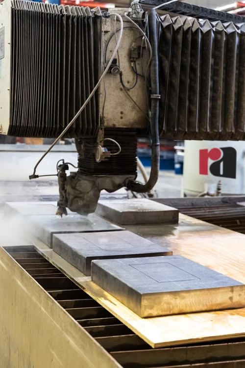
Material selection is only one part of the equation. The geometry of a component determines how well it can withstand cutting forces, clamping pressure, and changes in internal stress. Some designs are inherently more difficult to machine without warping, even when the material and machining process are well controlled.
Thin Walls and Large Pockets
Thin walls are among the most common reasons CNC-machined parts lose dimensional accuracy.
A thick block can withstand machining forces relatively well because it has greater structural rigidity. But when large sections are removed, the remaining walls become more flexible. This makes them more susceptible to deflection, vibration, and distortion.
Deep pockets create a similar problem. As material is removed from the centre of a component, the surrounding walls may become less rigid and more difficult to support. For example, a lightweight aluminium housing with deep internal cavities may be more susceptible to distortion or warping than a solid component of similar external dimensions.
Uneven Wall Thickness
When different sections of a component have significantly different thicknesses, they may respond differently to machining forces and temperature changes.
Thicker sections generally offer greater stiffness, while thinner sections are more likely to deflect. This difference can make it difficult to maintain flatness, parallelism, and alignment across the entire component. Where possible, designers should consider more uniform wall thicknesses or introduce structural features that improve rigidity.
Long and Unsupported Sections
Long, narrow components are particularly vulnerable to bending during machining.
If a component extends too far beyond its fixture, cutting forces can cause it to deflect. This may affect dimensional accuracy along the entire machined length. Designers and manufacturers should consider how the component will be supported during machining, not just how it will function in the final assembly.
Large Material Removal Ratios
The material removal ratio describes how much material needs to be removed compared with the original stock.
A component machined from a large block into a relatively thin structure may be more prone to distortion than one manufactured from stock closer to its final geometry. The greater the amount of material removed, the more important it becomes to consider residual stress, machining sequence, and structural support.
How to Prevent Warping During CNC Machining
Preventing CNC machining distortion requires a combination of material preparation, process planning, machining control, and inspection.
There isn't one technique that works for every component. The right approach depends on the material, geometry, tolerance requirements, and amount of material being removed.
Here are some of the most effective methods manufacturers use.
1. Start with Stress-Relieved Material
One of the most effective ways to reduce machining distortion is to start with material that has a suitable stress condition. Stress-relieved aluminium plates, stabilised castings, and appropriately heat-treated metal stock can help reduce the amount of residual stress that is released during machining.
For components requiring extensive material removal, intermediate stress-relief operations may also be considered.
However, stress relieving is not a guarantee that a part will remain perfectly stable. Its effectiveness depends on the material, previous processing history, treatment parameters, and the amount of stress remaining in the component.
2. Use Roughing, Semi-Finishing and Finishing Operations
Removing all the material in one operation is rarely the best approach for components with demanding dimensional requirements. A more controlled process separates material removal into stages.
- Rough machining removes the majority of excess material. At this stage, the focus is on efficient material removal rather than achieving the final surface finish or dimensions.
- Semi-finishing brings the component closer to its final geometry while retaining a controlled machining allowance. It also provides an opportunity for the material to stabilise before the final operation.
- Finishing removes the remaining allowance using lighter, more controlled cuts to achieve the required dimensions and surface finish.
This staged approach is particularly useful for large aluminium components, precision housings, and thin-walled parts.
3. Balance Material Removal Across Both Sides
Whenever the geometry permits, manufacturers should avoid removing most of the material from one side of a component before machining the other. Alternating between opposing faces can help reduce uneven stress redistribution.
For example, when machining a flat aluminium plate, a manufacturer may rough-machine one face, turn the component over, and remove a comparable amount of material from the opposite face before returning to the first side.
The objective is to maintain a more balanced material structure throughout the process. This approach is not always possible for complex geometries, but it should be considered during machining strategy development.
4. Optimise Cutting Parameters and Tool Selection
Cutting parameters have a direct influence on the forces and heat generated during machining.
Manufacturers need to consider spindle speed, feed rate, depth of cut, width of cut, tool geometry, and material characteristics together. Using an inappropriate tool or pushing cutting parameters too aggressively can increase heat, vibration, and workpiece deflection.
A sharp cutting tool with suitable geometry helps maintain efficient chip formation and reduces unnecessary friction. For demanding components, machining parameters should be validated through trials and adjusted based on actual part behaviour rather than relying entirely on standard recommendations.
5. Use Suitable Workholding and Support Fixtures
The workholding arrangement should keep the component stable without introducing unnecessary deformation. For thin-walled parts, custom fixtures, soft jaws, distributed clamping, and vacuum workholding can provide better support than conventional clamping arrangements.
In some cases, temporary support structures or sacrificial material can also help maintain rigidity during machining. The key is to ensure that the component is supported throughout the operation, especially as material is removed and its structural stiffness changes.
6. Control Temperature Throughout the Machining Process
Thermal management is particularly important when machining materials that are sensitive to temperature changes. Coolant delivery, cutting tool condition, machining duration, and the surrounding environment can all affect workpiece temperature.
For high-precision components, manufacturers should also consider temperature stabilisation before dimensional inspection. This helps ensure that measurements reflect the component's actual dimensions rather than temporary thermal expansion.
7. Allow the Component to Stabilise Before Final Finishing
Some components may continue to change shape after rough machining because residual stresses redistribute once material is removed and the part is released from its fixture. Allowing the component to stabilise before final machining can help reveal this behaviour before the final dimensions are established.
Depending on the material and application, this may involve an intermediate waiting period, a suitable stress-relief treatment, or another controlled stabilisation step. The process should be validated for the particular material and geometry rather than assuming that a fixed waiting period will work for every component.
CNC Machining Design Considerations to Minimise Distortion
Preventing machining distortion becomes much easier when the component is designed with manufacturability in mind. Design for manufacturability (DFM) considers how a part will actually be produced, including the material, machining sequence, tooling access, workholding, and inspection requirements. Here are some important CNC design considerations.
Maintain Adequate Wall Thickness
Thin walls are more susceptible to cutting forces and workholding pressure. Where possible, avoid making walls thinner than the application requires. A slightly thicker wall can significantly improve rigidity and reduce the risk of deflection during machining.
However, there is no universal minimum wall thickness for all CNC machined parts. The practical limit depends on material, wall height, unsupported length, machining method, and tolerance requirements.
Avoid Unnecessarily Deep Pockets
Deep pockets can reduce the rigidity of a component and make it difficult to support during machining. They can also require longer cutting tools, which may increase tool deflection and vibration.
Where possible, consider whether a pocket can be made shallower, divided into multiple features, or redesigned to retain more structural material.
Use Ribs and Structural Reinforcements
Ribs can improve the stiffness of thin-walled components without requiring a substantial increase in overall material usage. They help support unsupported sections and distribute loads across the component.
But, rib placement and thickness should be considered carefully. Abrupt changes in section thickness can create uneven stiffness and machining challenges.
Avoid Sudden Changes in Wall Thickness
Transitions between thick and thin sections can influence how a component responds to cutting forces and thermal changes. Gradual transitions are generally easier to manage than abrupt changes in geometry.
Where the design allows, use smooth transitions and consistent wall thicknesses to improve structural stability.
Consider Machining Access and Workholding
A part may look perfectly reasonable in CAD but become difficult to hold securely during machining.
For example, a component with multiple deep cavities and very few accessible clamping surfaces may require a custom fixture.
Designers should consider how the component will be positioned, supported, and machined at each stage. Involving the manufacturing team early can help identify these issues before production begins.
Specify Tolerances Based on Functional Requirements
Not every dimension needs the same level of precision. Applying unnecessarily tight tolerances across an entire component can increase machining time, inspection requirements, and production costs without improving its actual performance.
Instead, identify the dimensions that directly affect assembly, alignment, sealing, movement, or load transfer.
Flatness, parallelism, perpendicularity, and positional tolerances should be specified according to the component's functional requirements. This gives manufacturers a clearer basis for choosing the machining and inspection strategy.
How Do Manufacturers Detect and Measure CNC Machining Distortion?
A component can appear visually flat and still be outside its dimensional tolerances. This is why manufacturers rely on dimensional inspection rather than visual assessment alone. The inspection method depends on the geometry, tolerance requirements, and type of distortion being investigated.
- Coordinate Measuring Machines (CMMs)
CMMs use a probe to measure points across a component and compare the resulting geometry against the engineering drawing or CAD model. They are particularly useful for inspecting complex components, positional accuracy, parallelism, and dimensional relationships between features.
- Surface Plates and Height Gauges
A surface plate provides a stable reference plane for inspecting flatness and identifying bowing or uneven surfaces. Height gauges and suitable indicators can then be used to measure deviations at selected points.
- Dial Indicators
Dial indicators are useful for checking runout, surface variation, and alignment. They can help identify whether a component has developed a curve or shifted from its intended geometry.
- Optical Measurement Systems
Optical systems and non-contact measurement equipment are useful for inspecting delicate components, intricate profiles, and surfaces where physical probing may be difficult.
Why Should Parts Be Inspected After Unclamping?
This is an important part of machining quality control. A component may be dimensionally accurate while held inside the fixture because clamping pressure is temporarily keeping it in position. Once the fixture is released, the component may spring back or reveal distortion.
For this reason, inspection should consider the component in its free state, using an appropriate and repeatable measurement setup.
For precision applications, manufacturers should also allow the part to reach a stable temperature before final inspection. The inspection plan should clearly define the reference surfaces, measurement locations, temperature conditions, and acceptable tolerances.
Common CNC Machining Mistakes That Lead to Part Warping
Even well-equipped CNC machining operations can experience distortion when certain process considerations are overlooked.
Some common mistakes include:
- Removing too much material in one pass: Large cuts can increase cutting forces and make it harder to control deformation, particularly in thin sections.
- Ignoring the material's manufacturing history: Raw material with significant residual stress can distort as machining changes its internal stress balance.
- Over-clamping the workpiece: Excessive fixture pressure can deform the part temporarily and cause it to spring back after unclamping.
- Finishing one side completely before the other: Uneven material removal can contribute to stress redistribution and dimensional changes.
- Using worn cutting tools: Dull tools can increase friction, heat generation, and cutting forces.
- Skipping intermediate inspection: Distortion may develop during roughing or semi-finishing and remain undetected until the final inspection.
- Checking dimensions only while the part is clamped: This can hide deformation that becomes visible after the component is released.
Most of these issues can be addressed through better process planning, appropriate material selection, and closer coordination between design, machining, and quality teams.
Achieve Better Dimensional Stability in CNC-Machined Parts
CNC machining distortion is not simply a machine accuracy problem. It is a material, geometry, and process-control problem that needs to be addressed throughout the manufacturing cycle.
From selecting the right raw material and planning material removal to managing cutting forces, designing suitable fixtures, and inspecting components after unclamping, every decision can influence the final dimensional stability of a part.
For manufacturers, the objective is not just to machine a component to the correct dimensions once. It is to ensure that it maintains those dimensions consistently across production, after finishing, and when it reaches the final assembly.
At Wootz.work, we bring together machining expertise, manufacturing process control, and quality-focused production to help businesses source precision CNC machined components for demanding applications. Whether you're developing a new component or scaling an existing design, our team can help you work through material, geometry, and manufacturing considerations to achieve more predictable results.
Need CNC Machined Parts That Hold Their Tolerances?
Get precision-machined components with manufacturing processes designed around your material, geometry and dimensional requirements.
Request a QuoteFrequently Asked Questions
Why do CNC machined parts warp?
CNC machined parts warp when internal stresses, cutting forces, heat, or clamping pressure cause the material to deform during or after machining. Removing material changes the distribution of internal stresses, which can make a component bend, twist, or lose its original flatness.
How do you prevent warping in CNC machining?
Warping can be reduced by starting with suitable stress-relieved material, balancing material removal across both sides, using staged roughing and finishing operations, controlling cutting temperatures, and applying appropriate workholding. Part geometry also plays an important role, particularly when machining thin walls and deep pockets.
Why do aluminium CNC machined parts warp more easily?
Aluminium has a relatively high coefficient of thermal expansion and can contain residual stresses from rolling, extrusion, or other material processing operations. When large amounts of material are removed, these stresses can redistribute and cause the component to bend or twist. Thin aluminium components are particularly susceptible to machining distortion.
Does stress relieving prevent CNC machining distortion?
Stress relieving reduces internal residual stresses that can contribute to machining distortion. However, it does not eliminate every source of deformation. Cutting forces, thermal expansion, clamping pressure, and uneven material removal can still cause warping. The effectiveness of stress relieving depends on the material, treatment process, and component geometry.
What is the difference between residual stress and machining stress?
Residual stress refers to internal stresses that remain within a material even when no external force is applied. These stresses can originate from rolling, forging, casting, welding, or heat treatment. Machining-related stresses and deformation, on the other hand, can develop from cutting forces, friction, heat, and workholding during material removal.
How do you machine thin-walled parts without distortion?
Thin-walled CNC machined parts require careful workholding and cutting strategies. Manufacturers can reduce distortion by using suitable support fixtures, lighter cutting passes, sharp tools, optimised toolpaths, and staged material removal. Maintaining sufficient wall thickness and avoiding excessive clamping pressure are equally important.
Can CNC machining distortion happen after the part is finished?
Yes. A component can change shape after machining when it is unclamped and previously restrained deformation is released, or when residual stresses redistribute. Cooling can also change its measured dimensions through thermal contraction, although this does not necessarily indicate permanent distortion.
This is why precision components should be inspected after unclamping and, where necessary, after thermal stabilisation.
Which CNC machining materials are most prone to warping?
Aluminium alloys are particularly susceptible to distortion when machining large plates and thin-walled components because of their thermal expansion and potential residual stresses. Plastics can also deform under heat and clamping pressure. Stainless steel, titanium, and carbon steel can experience distortion too, depending on their material condition, geometry, and machining process.
What is the best machining strategy for large aluminium parts?
A staged machining strategy is generally preferred. It involves roughing the component, distributing material removal across opposing faces where possible, allowing the material to stabilise, and then carrying out controlled finishing operations. Starting with suitable stress-relieved stock and using appropriate workholding further reduces distortion risk.
How do you check flatness in CNC machined components?
Flatness can be checked using a surface plate and dial indicator, a coordinate measuring machine (CMM), or suitable optical measurement equipment. The component should be measured in a consistent, properly supported condition, ideally after unclamping and temperature stabilisation. The measured deviation is then compared against the flatness tolerance specified in the engineering drawing.
Does machining sequence affect dimensional accuracy?
Yes. The order in which material is removed affects the stiffness and internal stress distribution of the remaining component. Roughing, semi-finishing, and finishing in planned stages can help reduce distortion. For suitable geometries, alternating between opposing faces also helps distribute material removal more evenly.
What is the difference between machining distortion and tool deflection?
Machining distortion refers to a change in the component's geometry due to stress redistribution, thermal effects, or mechanical forces.
Tool deflection occurs when the cutting tool bends under cutting forces, causing it to deviate from its programmed path. Workpiece deflection can also occur when the component itself moves during cutting. All three can affect final dimensional accuracy, but they require different corrective measures.


